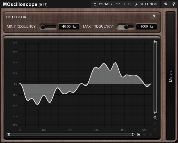
This online virtual oscilloscope allows you to visualise live sound input and get to grips with how to adjust the display. If you find this useful, our online spectrum analyser may also be of interest to you.
A software oscilloscope made for looking at music. Drop an audio file in the application and watch the waveforms. Windows 1.0.8 (Jan 23, 2017) Mac OS X 1.0.8 (Jan 23, 2017) Linux 1.0.3-prerelease; device selection not working (Mar 5, 2016) Source; The new version isn't tested much.
An oscilloscope is a useful tool for anyone working with electrical signals because it provides a visual representation of the signal's shape, or waveform. This allows you to measure properties of the wave, such as amplitude or frequency.
- Real-time Spectrum - Our Choice. Displaying real-time waveform. Lightweight tool.
- Oscilloscope, Arbitrary Waveform Generator, Spectrum Analyzer, Logic Analyzer, Digital Pattern Generator. Software, firmware and hardware sources are available for free. All under open source license. Software runs on Windows, Linux and Mac. 2 analog oscilloscope channels (10-bit).
The initial signal above is a 200Hz sine wave, which has an amplitude of 5 volts. The frequency of this wave can be adjusted by using the 'Input Wave Frequency' slider.(You can also choose to display a square wave.)

If you are browsing using the latest version of Google Chrome, the input dropdown box allows you to select 'live input'. This will take data from any microphone connected to your computer and display the live audio data. (Different microphones send different voltages to the computer, so for consistency we have normalised the input so the raw input signal will always be limited to somewhere between -5 and +5 volts.)
Since waveforms come in a wide variety of shapes, amplitudes and frequencies, oscilloscopes need to have a number of controls to adjust the display of the waveform so it can comfortably fit inside the viewport.
Freeze live input
This tickbox freezes the input allowing you to effectively take a snapshot of what is displayed on the oscilloscope at a given instant in time. This is especially usefulbecause you can still adjust the time base and volts per division setting. Try whistling and freezing the input. Adjust the timebase to a convenient scale allows you to calculate the frequency of your whistle by counting the period of one complete waveform.
Oscilloscope gain
This is a number that the incoming signal is multiplied by. A gain of 1 will have no effect, a gain of less than 1 will make the signal smaller and a gain of more than 1 will make it larger.
seconds / div
This control allows you to adjust the length of time that each square of the grid represents. When the oscilloscope is first loaded, this setting is set at 1ms, and shows one complete waveform over 4 squares. This means that the period of the wave is 4ms, or 0.004s, giving a frequency of (1/0.004) = 250Hz. If you change the timebase to 500µs (half of what it started at), you should see the waveform now takes 8 squares to complete one full oscillation. The period (and hence the frequency) remain constant because 8 times 500µs still equals 0.004s.
volts / div
This setting is very similar to the timebase setting described above, but instead of stretching the wave along the x-axis, it involves stretching it along the y-axis. The sine wave has an amplitude of 5V, meaning when volts/div is set to 5, the waveform just reaches the top of the first square. If you were to change the setting to 10 volts/div, the waveform now only reaches up half of a square.
Horizontal and Vertical Offsets
These two sliders allow you to adjust the position of the oscilloscope's trace on the grid. They are particularly useful for lining up parts of thewaveform with the gridlines (this can make it easier for you to count the squares when determining wavelength, for example).
Oscilloscope App Free
If you would like to embed the oscilloscope on your own website, please copy and paste the following html onto your web page.
Oscilloscope App Ios
